 and Trim
The ballistic calculator employs the traditional momentum drag equations for each arrow component. Superimposed on this drag are tapered drag corrections for resonant shaft vibration, rotation oscillation and spin.
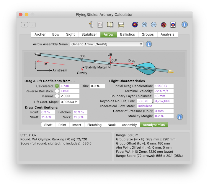
Select the working drag coefficient of the arrow from one of three sources. In general, the calculated version is fine as changes to the arrow configuration will ripple thought. The area term in the drag equation is based on the shaft's maximum diameter - see the FlyingSticks booklet for a discussion.
The Drag Coefficients are normally in the range 1.5 to 3.0, however for large LARP type "points", values ten times greater can be expected. This is due to the fact that we have based the Reynolds Number (see below) largely on the shaft dimensions, not the point diameter. This allows simpler comparison of various points.
and TrimThe calculated drag coefficient is a theoretical value at launch. It is based on the arrow's configuration, dimensions, airspeed and atmospheric conditions. It may be manually trimmed by up to ±100.0% using the adjacent "Trim" field.
Note: the calculated drag coefficient is based on the Reynolds Number at the launch air speed. When the air speed is below 10 m/s, it is assumed to be 10 m/s in calculating the Reynolds Number. This can occur with unrealistically strong tail winds. The wind speed is defined in Ballistics>Atmosphere panel and is enabled by the wind drift checkbox state.
The primary measured value from the reverse ballistics calculations in the Sight>Ballistics panel. If the reverse ballistics are not available or are not sensible, then the above theoretical value is substituted.
Enter any value between 0 and 10.0. This provides a direct way to test the impact of arrow drag changes. Good for general "what if" investigations.
Enter the lift coefficient's slope term. This defines how the lift coefficient changes with yaw and pitch angles. The value is used to determine the lift and induced drag on a rotated arrow. Up to about 8° the lift coefficient increases linearly with pitch angle.
A good stating point is a value that has been measured in wind tunnel test (Takeshi Miyazaki et al) as 0.0056 CL/° when the area term is taken to be the effective lift area as opposed to the shaft cross-sectional area used in their study.
Four calculated drag contributions from the arrow's point, shaft, fletching and nock. It should be noted that because of the complexities of arrow aerodynamics, these contributions are indicative as they tend to ignore interaction between components.
The point usually contributes about 5% total drag for target and field points although this may drop to under 2% for a well launched streamlined point. The point contribution can rise to 30% for complex broadhead and higher still for snarling and LARP points.
Fishing points with a trailing filament lines are not modeled accurately. No account is taken for the air drag on the ever increasing length of line or the additional drag in involved in accelerating the feed line. However, bow fishing is usually done at short ranges, so these details are the least of one's concern.
As might be expected the shaft is the largest contributor - typically 65-80%. Thinner and barrelled shafts will reduce the figure.
The modern target fletches are relatively low drag - typically contributing 10% to 20% of total drag. Flu-flu can be much higher. Their weather-cock action is mainly due to the fletches' lateral lift.
The nock drag is typically 10% of total drag. This is a figure that may be improved by better aerodynamic form, especially with a long shaft taper meeting a small diameter nock.
As the results are dependent on the Reynolds Number at launch, they can be seen to change a little with wind speed.
This is the drag induced deceleration an arrow experiences on leaving the bow. It includes the effects of the current wind conditions.
This is the calculated speed that the vertically free falling arrow will eventually reach. It is the condition where gravitational force is equal and opposite to the aerodynamic drag force. The value presented here is based on a Drag Coef. calculated for the launch air speed (i.e. launch speed plus wind speed), not the terminal velocity, so it will be seen to change a little with bow draw weight and wind speed.
This field indicates the approximate thickness of the shaft's turbulent flow boundary layer at the fletches. Interestingly if the fletches were in "clean" air, their flow is likely to be lamina, however they are at least partly in the shaft's boundary layer, so the flow is likely to be mixed. This is further complicated by the arrow's resonant vibration and yaw / pitching oscillation, both of which will modify the boundary layer envelop relative to the shaft.
Two calculated Reynolds Number fields using the shaft diameter and shaft length as the reference lengths. The Reynolds Number (Re) is a dimensionless figure used to compare similar shaped objects of different sizes in different fluids. There is some confusion over the so called reference length - some use the arrow length while more commonly the shaft diameter is preferred. The choice tends to depend on the purpose for which it is used. FlyingSticks generally uses the diameter based version.
Of special interest is the transition from lamina to turbulent flow. For a typical target arrow this transition progressively occurs for ~10,000 < Re < ~22,000, were the front part of the arrow may experience lamina flow, but at some point along the shaft will break down to turbulent flow. The point where this occurs is very sensitive to a range factors, including surface contamination by grit or mud.
Associated with the transition is a steep change in the arrow's drag coefficient, typically moving from 1.6 to 2.5. This can have a serious impact on grouping - see the eBook>Aerodynamics and the comments below for more details. In general it is best to encourage full turbulent flow. The Reynolds Number fields are shown in red in this transition range.
The calculated CoP is the point on the arrow where the combine aerodynamic forces on an arrow are seen to act for a highly pitched arrow. The position is measured relative to the arrow's length wise center, negative if rear of center. The CoP moves forward as yaw or pitch angle increase. At very low angles the CoP is likely to be just forward of the fletches, but at high pitch is likely to be closer to the arrow center - which is the value shown in this field. It should always be rear of the CoG and FoC for absolute stability.
An arrow may be conditionally stable below a certain angle of attack, but increasing the angle of attack moves the CoP forward of the CoG and into an unstable region.
This calculated field provides a better indication of arrow stability than the traditional FoC as it takes into account the location of the CoP and the length of the point and nock. The stability margin is calculated:
stability margin = (CoG - CoP) / L
where L is the arrow's aerodynamic length.
Higher positive (CoG in front of CoP) values are more stable. Negative
values indicate conditional stability or out-right instability and can
be dangerous - the arrow is likely to veer off course, in some cases
wildly. For this reason, the field will display in red when below 5%,
allowing a small safety margin.
Point aerodynamics is complicated by how they initiate the development the arrow's aerodynamic boundary layer. Counter intuitively, some theoretically low drag points may increase arrow drag by delaying the development of a turbulent boundary layer and worst, making the laminar – turbulent transition sensitive to the point's angle to the air-stream. This in turn introduces a variability factor dependent on arrow flexing, fishtailing, cross winds and surface contamination.
Arrow flexing or resonance induced by finger releases and offset bows usually guarantee turbulent flow. Mechanical releases in conjunction with center-fire bows and stiff arrows may not ensure turbulent flow so a decidedly "non-aerodynamic" point may be preferred.