
Knowing the bow's sight geometry allows FlyingSticks to calculate a bow's energy performance and to generate range tapes. Measurements should be done with ±1 mm (±1/16") or better accuracy for best results.
Before taking the measurements, sight the bow and arrow combination, ensuring that the sight pin is able to safely cover ranges the required ranges (typically from 8 to 90 m (10 to 95 yd)). The maximum range may need to be reduced with lighter bows or heavier arrows.
Some measurement must be made on a drawn bow with the aid of an assistant. This is DANGEROUS so great care needs to be taken. It is recommended that measurements B and C be taken by marking on paper then measuring away from the bow.
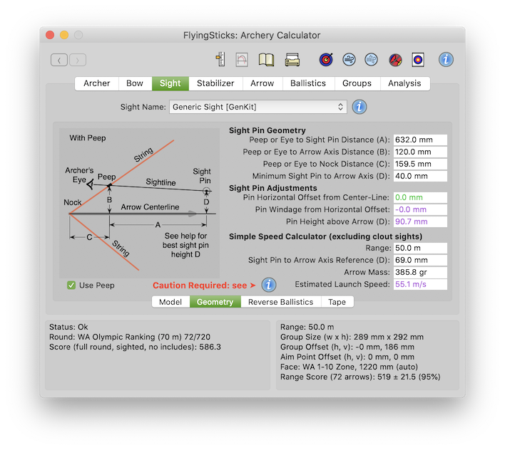
If a peep is used, ensure the box is checked. The image will then show the measurements required for set-up.
This is the distance parallel to the arrow between the sight pin and the peep or eye.
This is the height of the peep or eye above the arrow axis, measured at right angles to the arrow's axis. Take great care to achieve an accurate measurement SAFELY. Use a sheet of paper to ensure the right angle and mark peep or eye position above arrow wall. Also mark on the arrow position of the peep or eye. Away from bow measure the distance and add arrow radius.
This distance should be as large as comfortably possible as it impacts the maximum sight tape range. See the FlyingSticks eBooklet for establishing the optimal peep height.
This is distance along the arrow to right angle line to the peep or eye. It corresponds to the distance between the mark on the arrow placed in previous step and the arrow's nock point.
An important parameter that determines the maximum range that the sight is safety capable of without the launching arrow interfering with the sight. It is measured by setting the sight barrel as close to the arrow's path as possible without arrow shaft or fletching interference. One should bear in mind that an arrow may be flexing vertically on release from some bows, especially older compound bows. Check for clearance as recommended elsewhere. Once comfortable with the setting, measure distance from sight pin to the arrow axis. Typical value would be 30 mm plus the radius of the sight tube.
You may set values lower and even negative values (i.e. below the arrow axis) to get a feel for what wound be needed for clout sighting without a clout sight-line deflector. Values less than 35 mm without a clout sight attachment will show in red as a warning of a dangerous setting.
If a clout sight attachment is fitted, this field is ignored. Instead, the lowest position assumed is that required to achieve 90% of the standard (no wind) flight range.
Variables or parameters that are adjustable, either manually or automatically.
The calculated sight pin's lateral offset from the bow's center-line. It reflects the arrow's launch direction due to the current internal ballistics. Positive to the left for a right-handed bow and visa versa.
Ideally this offset would be zero. Indeed, the usual aim of bow tuning is to ensure it is zero. For non-center-line bows or with finger releases, this sometimes may not be the optimal value. FlyingSticks' modelling the internal ballistics - spine matching, arrow rotation and arrow resonance all impact the calculated value.
This provides the sighting correction of the sight point for wind drift. It direct interacts with the launch azimuth. Re-sighting will set the windage required for the current wind and range.
The sight pin height calculated by the most resent re-sighting operation.
For non-clout sights only. Requires the above A, B and C dimensions to have been entered.
This is the actual range that corresponds to the Sight Pin to Arrow Axis Reference point measurement below. A reference mark at this range will be placed on the range tape as an "x" if it is within the tape's minimum and maximum ranges. Forty to fifty meters is a good value.
The first step is to setup the reference sight pin height. This is somewhat arbitrary as it can be used to provide a reference point for subsequent tape scale measurements (e.g. for reverse ballistics measurements) and for the location of the printed range tape.
The recommend approach is to set the sight point to a known range for the arrow - 50 m (50 yd) is a good number! This point should be marked on the sight's scale with a fine line marker pen. When a tape is printed a reference line and an "x" will be included and it should be aligned with this mark on the scale. (This point on the scale is the datum for the Reverse Ballistics data).
For target shooters where the sight frequently extends well beyond the drawn arrow point, this measurement is more difficult. Use a ~3 m ( ~3 yd) cotton thread looped over the arrow's nock. Attach a weight to the other end and extending in front of the archer over a support such that the weight will keep the cotton line taught. Orientate the drawn bow so the line becomes an extension of the arrow's axis. The measurement can be made by attaching a rule to the sight and taking note of the distance.
DO NOT allow your assistant to measurement in front of the firing line.
This is the arrow mass for which the above reference sight pin and range were measured. It is for record purposes only, although could be used for a preliminary bow energy and speed estimates for other arrow masses.
From the above data, the average speed over the range is calculated, then a correction for typical arrow drag is applied to achieve a launch speed estimate.
You will notice the speed is very sensitive to the difference between the B and D measurements, so it is important that these measurements be as accurate as possible. The Reverse Ballistics panel provides greater accuracy if you are prepared to collect the additional data required.
The vertical "Peep or Eye to Arrow Axis Distance" needs to be carefully established as it is an important contributor to archer's form calculations. It needs to be as comfortable and repeatable as possible. If the distance is too small the sight pin may come dangerously close to the arrow's path.