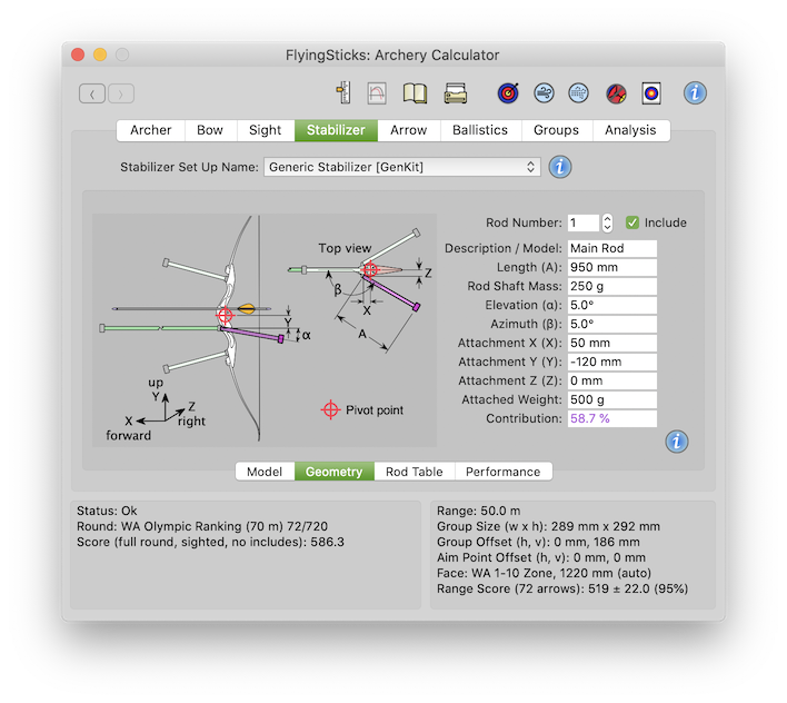
 Include
Stabilizers aim to improve grouping by a combination of reduced sighting wobble and better internal ballistics. They are most definitely not a substitute for good form. A secondary function can be to reduce noise and vibration; however this can compromise the primary function.
This section of FlyingSticks provides understanding on the use of stabilizers in the reduction of sighting wobble. The impact on internal ballistics is not cover but may be partially dealt with during fine tuning.
Stabilizes can be configured in numerous ways. It is import to be absolutely clear about the goal - better grouping - but the path to get there is not always so clear.
The sighting wobble model used in this section assumes the archer's arm, the drawn bow, sights and stabilizers function as one rigid structure pivoted about the archer's shoulder. (one could argue that the upper part of the torso is also part of the system, pivoting at some point on the spine). Technically the wobble is related to the system's moment of inertia which is proportional to the sum of each individual mass multiplied by the square of its distance from the shoulder. Increasing the moment of inertia will reduce both the amplitude and the rate of movement of the wobble.
Added weight also moves the center of gravity (CoG) which also need to be optimized, usually placed a little in front and below the riser's pivot point.
Most fields are compulsory unless specifically indicated otherwise. If a field is not sensible the rod may be excluded from calculation and the "Contribution" field will indicate 0.00%.
The data fields in this panel are identical to the columns in the Table tab, with the rod number being the column number:
Up to 5 stabilizer rod and weight details may be entered. This field selects the one to be edited.
IncludeThis check box indicates if the rod and weight is attached and being included.
This field is used to identify a rod in the database so should be unique unless it is shared with another configuration. In a complex setup would typically indicate position e.g. "Top Short RC1".
Rod length from attachment point to the center of gravity (CoG) of end weight as indicated in diagram.
The weight of the rod without the end weight. The CoG of the rod is assumed to be at 45% of its length from the attachment point.
Angle in vertical plan above arrow axis. Positive up, negative down.
Angle in horizontal plane from arrow axis. Positive to the right, negative to the left. For rear facing "V" rods, the angle is measured from forward arrow position, so this angle is 180° minus the "out" angle.
Defines the attachment point relative to the riser's pivot point along the horizontal or arrow axis. Positive forward of the pivot point, negative towards archer.
Defines the attachment point relative to the riser's pivot point in the vertical direction. Positive above the pivot point, negative below.
Defines the attachment point relative to the riser's pivot point in the horizontal direction. Positive to right of the pivot point, negative to the left.
The mass of the attached weight.
This is a calculated field showing the contribution of this rod and mass to the wobble stability of the bow.
The calculations to determine the stability improvement assumes the rod, its weighted end, the bow and the archer's bow arm are one rigid mechanical system. No allowance is made for flexing.