
This Sight Tape facility allows the printing of a range reticle customized for your bow and arrow combination. Note that the calibration is very dependent on the arrow mass and to a lesser extent the arrow's drag coefficient. Thus a tape is required for each sight, bow and arrow combination.

The tape data is saved as part of the sight's information - thus different tapes should be saved as different sights or better, as different kits.
If the target center height above ground is set between 0 to 1.5 m, that height is used for tape generation; otherwise the default of 1.3 m is applied. The affect of target center height is small but noticeable.
The sight geometry is measured with the sight setup for a reference range. This range would typically be selected in the 40 to 70 m (or yards) span. The measurement process involves placing a mark on the sight scale bar corresponding to this range, or simply leaving the sight pointer set to this range. This mark becomes the datum and should line up with the datum placed on the tape (a "x" at the reticle range).
The measurement units on the tape are the current defaults appropriate for each related field, however the main scale units take those of the current range units.
This provides a zoom-able and scrollable view of the current tape.
The default font is "Helvetica", however it may be changed in the Preferences Panel's "Font for Tapes, etc." filed. Any font available on your computer may be select when the "Show Fonts" item is selected.
Keep the Tape view or the Tape Wind visible while selecting the font to immediately see the results of a font change.
Provides a drop-down menu of simple color schemes. The selected scheme is saved with the tape description. If a new Tape Style (see below) is selected, the style's color scheme will be loaded, possibly requiring a re-selection of your preferred color scheme.
Note: When the tick marks fall below the Minimum Pin to Arrow Axis height, the ticks and range labels will be in red indicating possible arrow contact and a safety issue.
Zoom (over a x0.25 to x4.00 span) by dragging the magnification slider below the view, or simply click on a position on the slider. The view allows the inspection of fine details before printing.
The text below the slider shows the magnification (e.g. Magnification: x1.50). Clicking on this text will return the magnification to x1.00.

Open Tape Window and bring to front. A click on the tape will open the calculator's Sight>Tape panel where tape parameters may be changed. This window is updated whenever a kit component is changed, so is useful to gauge for the practical impact of modifications.
 The
button will be greyed out if the sight is disabled in the Bow>Model
panel.
The
button will be greyed out if the sight is disabled in the Bow>Model
panel. 
If not already visible, will open the Tape window, then the standard print dialog from where the tape may be forwarded to a printer or saved as a PDF file for later printing. In general, it is recommended that you save as a PDF then print the PDF.
Whatever method used, you should confirm the scaling is perfect by adjusting the Print Scale Trim (below) for accurate sizing. Several attempts may be required. This button also saves Print Scale Trim should re-instating be required.

Several predefined tape styles are available - choose the one that best suits. The styles tend to be optimized around tape width, and various tape features are a proportion of the width.
When selecting a style, the tape width, tick marks and font size will be set to the style's default values. These may then be modified to suit your requirements and will be active until you again select a new Tape Style.
For multi-pin styles, the tape becomes a pin spacing template where the major tick marks become the pins and some fields change their action a little for a more intuitive process. Range span bars are added to each pin to give a "feel" for the range coverage of the pins. A faint grey circle indicates the approximate sight barrel outline. See the
"More on Multi-Pin Templates" below and "Setup a Multi-Pin Sight" how-to for more details.
The Tape Style details are part of the sight, so to save a tape setup, save it as a new sight.
Enter the number of pins in the sight barrel. The field mirrors that in the Sight>Model panel. Tape Styles, other than multi-pinned, force the value to 1.
The maximum range to cover on the tape. The units of this field determine units on the tape's main scale. The format and layout is optimized for meters and yards. Other units may have unexpected results, but small changes to the maximum or minimum range fields, or the major tick field may produce a better tape.
The Pin field is the height of the sight pin above the arrow's longitudinal axis for the maximum range. The sight pin is assumed to be that of a simple sight - not a pivot or pendulum type, although the pin position is corrected for clout sights if enabled. Will be in red if below the minimum safe height. Automatically adjusted for clout attachments.
If the maximum range is not achievable due to the sight pin being too close to the arrow axis (see Minimum Pin to Arrow Axis (Dmin) in Sight>Geometry tab), then the questionable part of the reticle will be shown in red. Never use a tape with a red reticle or range labels.
For multi-pin sights the maximum range may be limited by the number of pins.
The minimum range to cover on the tape. If the Range Below Turnover check box is not checked, then the value will be the greater of the minimum range or the turnover range (see Range Below Turnover below).
For multi-pin styles, the minimum range pin is set to the nearest half Major Tick spacing i.e. for a 10 m spacing the minimum range will be on 20, 25, 30, 35 ... etc. thus allowing for 25, 35, 45 and 55 pins.
The Pin field is the height of the sight pin above the arrow's axis for the minimum specified range (excluding pivot and pendulum sights). Automatically adjusted for clout attachments.
For indicative purposes only, these fields show the calculated turnover range and the associated sight pin height above the arrow's axis. The scale for ranges below this value move back over the main scale, potentially creating some confusion.
Show the calculated sweet range. 3D shooter and hunters may find this useful. For multi-pin styles, the sweet range is assumed to be the first (top) pin if "Include Sweet Range" is checked.
The Tolerance is the acceptable target offset error used to determine the sweet range and other range spans. This is particularly useful for multi-pin sights in establishing the range span coverage of each pin and hence the optimal pin spacing. A default of ±25 mm is set when ever the Tape Style is changed. The tolerance can be set in the Ballistics>Extras panel or when the "Kill Zone Diameter Link" checkbox in the Hunting>Game panel is checked, then the Tolerance will be set to one third of the Kill Zone Diameter value for the selected game type.
The Major Tick is field indicates the preferred interval between major scale ticks. The value is taken as a guide only as the tape formatter aims to place ticks on major whole numbers. For multi-pin sights, the major tick spacing becomes the pin spacing.
Enter the number of minor ticks between each major tick. Generally best left at the default 10 minor ticks per major. Depending on the Minors-per-Major number, the tape formatter may place some slightly larger minor ticks to make the tape more nuanced.
Width of the printed and cropped tape. You should ensure it is set to the maximum the sight scale frame can accept. Many features of the tape will change proportionately with the width - e.g. the tick lengths are defined as a proportion of tape width by the selected Tape Style.
The cropped length of the tape. This is the exact length that should be printed otherwise the reticle will be in error (see Print Scale Trim to adjust). The tape length may be automatically increased if needed and will be rounded to a sensible value based on the length units. This makes checking with a steel rule more precise.
If the Auto Tape Length box is checked the tape will always be set as FlyingSticks thinks best. If unchecked, the field may be adjusted manually, however if set much too short, then it will auto adjust.
If clout attachment is fitted, the tape is allowed to drop below the axis
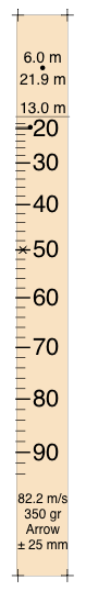
The tape is printed surrounded with a cropping area - the area outside the cropping marks that optionally may contain some descriptive text. This margin also helps space tapes on a page when multiple tapes are printed. The minimum crop margin is 0 mm, however to prevent congestion, below 3 mm crop text is not included. Defaults to 5 mm (20 mm for multi-pin) when Tape Style is changed. The figure below shows a tape cropped and ready for use.
If the "Center Vertically" check box is un-checked, allows the reticle to be offset from the center of the tape. A positive value moves the redicle up, a negative value down.
Enter font size (height) of the range numerals. The remaining text is given a size that is a proportion of this size, depending on the tape style. Changing the font (in Preferences) will change the type face that may have a different numeral size for the same nominal font size.
Allows the addition of a few descriptive characters to the tape. As a matter of interest, you may include various symbols from Edit>Emoji_and_Symbols when this field is selected.
The following options can be checked for additional information to be placed on the tape or to change the reticle orientation:
Checking will include launch speed, the arrow mass, custom text and for multi-pin sights, the target tolerance.
If the arrow mass appears in red, then the current mass is below the safe limit for the bow. Avoid.
The target tolerance is only included if the "Include Sweet Range" checkbox is also checked.
Checking will include the turnover line and associated range text in user's preferred units. If "Range Below Turnover" is checked, then this check box will automatically be checked then disabled (greyed out to prevent further change).
The geometry of the sights and the ballistic path of the arrow produce a range scale that doubles back on its self at short ranges. Left unchecked, this option limits the minimum range to the turnover inflection point, resulting in less ambiguity.
If checked and the minimum range is less that the turnover range, then a second scale reticle is printed. This widens the space required to print the tape - which will be an issue for narrow tapes.
In general the reticle becomes confusing with the inverted second range scale so is best avoided.
The sweet range is a single sighting point that covers the widest possible span of ranges with a definable tolerance on the target. See "Sweet Range, Tol." above or the Ballistics>Extras panel's "Target Tolerance" for setting the tolerance. For hunting the tolerance may also be linked to the game kill zone size in the Hunting>Game panel.
Most useful for small game hunting and close range 3D, especially with moving targets. Increasing the tolerance from the default ±25 mm (1") to ±75 mm (3") may be useful for larger game. It should be noted that this tolerance does not include the uncertainty of the archer's form.
Checking the box marks the range sweet spot on the reticle with a dot and prints the range span text at the top or bottom of the tape. The format on the tape is dependent on the selected Tape Style. For multi-pin styles, a range span bar is shown as for other pins, but to minimize confusion only ranges above the turnover range are included.
For multi-pin sights, the sweet range is allocated the first (top) pin.
More on the range sweet spot is found in Ballistics>Extras.
If checked, will delete the least significant digit of the tape's range label. This is done by simply dividing the range by 10, and then rounding the result. If the clipped digits are not zero, then obviously the label will be confusing. This facility is a space saver for narrow tapes.
Reverses the tape with a horizontal flip. Some styles may reverse better than others.
Reverses the tape with a vertical flip about the center point. Some styles may flip better than others. Flipping vertically is equivalent to changing the sign of the Scale Multiplier in the Sight>Geometry panel.
If checked, will zero the "Offset from Center" distance so that the reticle is centered on the tape. This will provide a good starting point for a tape layout.
The tape will be lengthened if it is too short to fit the reticle and the reference make (cross) omitted.
If checked, will place descriptive text in the crop margin area for margins greater than 3 mm. The text includes the bow name and draw weight, arrow name and weight, launch speed and drag, temperature, altitude, FlyingSticks app version, the date and time the tape was generated, the tape length and printer trim factor.
If checked, will automatically adjust tape length to required, rounded upwards to sensible value in current units. The rounding makes it easier in measuring the printed tape for printer scale calibration.
By entering the actual last printed length in this field, the above calculation will be done when the field is entered. Initially and after a tape print, the field will be set to ##### indicating a new value needs to be entered if the current printed tape is incorrectly scaled.

If an incorrect value is entered in the Last Printed Length field, click this button to start afresh. The Printer Scale Trim will be re-instated and the Last Printed Length field set to #####. When a tape is printed, its Printer Scale Trim will become the new re-instate value.
Allows fine adjustment of the printed tape's size. Typically, printers can be a few percent out, so measure the printed vertical distance between the crop makes and adjust the Print Scale Trim until it matches the specified Length to within 0.1 mm.
You can use the following formula to calculate the trim:
trim = 100 x (required_length - measured_length) / required_length)
where the units are assumed to be percentage. When the Last Printed Length field (below) is entered, this calculation will be done for you. FlyingSticks remembers the Trim between launches so the trim process may only need be done once for a particular printer.
Sets the number of tapes to print on a page and opens the Tape Window when a value is entered. The function is also available in the lower left corner of the Tape Window. The set of tapes is printed as in a single row, centered on the page. Use the crop margin to adjust the tape spacing. The maximum number of tapes is dependent on the tape and paper widths.
The multi-pin sight tape style produces a template for setting the pins of the sight. The tape has some variations on the normal tape that are aimed at provided a feel for the effectiveness of the chosen pin layout.

An example to the right shows a template tape for a three pin sight covering ranges from 2 yd to over 45 yd.
The target tolerance is printed at the bottom of the tape and can be linked to the game kill zone size in the Hunting>Game panel. It is used to determine the sweet range and the pin range spans.
The sweet range set point can be allocated to the fist pin if the Sweet Range check-box is checked. This will also include the minimum and maximum of the sweet range printed towards the top of the tape. In the example template the sweet range is from 2 to 27 yd with a target tolerance of ±3".
Range span bars are added to the pin ticks to give an indication of the span of ranges covered when sighting on the pin. Within the range span bar may be seen marks that show a reduced a range span that reflects the archer's form or grouping skills.

The span range bars are an important guide in optimally placing the pins for the most intuitive sighting.
When the archer's form in inadequate or an ethical kill is unlikely, then an ethical problem mark (red cross within a circle) is added to the pin tick.
Set the minimum range field for the top pin or second from top if Sweet Range is checked. Usually it would be 25 to 35 yd (or m). The internal value will be rounded to the nearest 5 range reticle units (e.g. 25, 30, 35, 40, etc.).
When the sweet range pin is enabled, it is not rounded as for other pins. You may like to manually round by noting the sweet range set point, setting the minimum to its nearest rounded value then disabling the sweet range.
Use the Major Tick or Pin field to set the range between pins. Internally this value is rounded to whole number in range reticle units. The Minor Tick field is ignored.
Re-adjust the above settings such that the gap between range span bars is approximately equal.
In the background, a light grey disc shows the approximate location of a 45 mm sight barrel. It is placed to center the pin-set within the barrel and is not adjustable. Changing the cropping margin can make more of the disc visible.